

AOE3054 - Experiment 5 - Material Testing
Experiment 5 - MATERIALS TESTING
Last modified 13 Nov 2025
1. Introduction
Polymer bonded explosives (PBXs) are particulate composite explosive materials, consisting of explosive materials present in the form of orthorhombic or monoclinic crystals in a polymer binding matrix (see Figure 1). Crystals are typically made of HMX (cyclotetramethylene-tetranitramine), RDX (trinitroperhydro-triazine), TATB (triamino- trinitrobenzene) or PETN (pentaerythritol-tetranitrate), while the polymer matrix is typically constituted of epoxy, estane (thermoplastic polyurethane), HTPB (Hydroxyl-terminated polybutadiene), Viton-A (fluoropolymer binder), Kel-F (poly(chlorotrifluoroethylene-covinylidene fluoride), PDMS (Polydimethylsiloxane).

Figure 1. Scanning Electron Microscope micrographs of the fractured surface of AP-AL-CNT 2% PDMS composites embedded in a PDMS matrix, highlighting key microstructural features: aluminum (AL) particles (blue), and ammonium perchlorate (AP) crystals (orange). The distribution and morphology of each component indicate heterogeneous dispersion.
Polydimethylsiloxane (PDMS)-based polymer-bonded energetic (PBE) composites incorporating ammonium perchlorate (AP) particulates represent a flexible and compliant class of energetic materials in which oxidizer crystals are embedded within a viscoelastic silicone binder. These materials experience a wide range of mechanical and thermal loading conditions, including accidental low-velocity impacts during transportation and handling, as well as vibration, cyclic stresses, and temperature fluctuations during launch, flight, and landing operations. Such stimuli can generate localized regions of elevated temperature—commonly referred to as “hot spots”—which may act as ignition sites at the microscale. To examine these effects under controlled laboratory conditions, artificial hot spots are created by focusing a laser on the specimen surface, enabling the study of thermally induced initiation and localized heating behavior. In addition to mechanical characterization, the samples are subjected to thermal analysis to evaluate temperature-dependent changes in material response and stability, simulating the thermal gradients encountered during actual flight. Because inadvertent initiation from combined mechanical and thermal stimuli poses significant safety concerns, understanding the coupled thermo-mechanical behavior of AP–PDMS composites is essential for assessing their structural integrity and reliability in operational environments. This area of study has been a central focus of ongoing research within Dr. Gary Seidel’s group in the Virginia Tech Department of Aerospace and Ocean Engineering, particularly with regard to improving the safety, stability, and multifunctional performance of energetic composite materials.
While AP–PDMS composites provide valuable insight into the behavior of compliant energetic binders, their fabrication is complex and costly. The curing of PDMS requires metallic molds to withstand elevated curing temperatures and ensure dimensional precision, and its high viscosity during mixing makes uniform AP dispersion challenging. To overcome these limitations, epoxy-based systems are adopted as a more practical and economical alternative for large-scale specimen preparation. In this work, a thermoset epoxy binder is employed, which can be cast and cured in reusable silicone molds—simplifying production, improving reproducibility, and reducing fabrication costs. The lower viscosity of the uncured epoxy facilitates homogeneous particle dispersion, while the curing process is readily controllable without the need for high-temperature metal tooling. Although epoxy forms a stiffer and more brittle matrix than PDMS, it enables consistent specimen geometry and reliable bulk production, making it well-suited for systematic mechanical testing and comparative studies.
To maintain structural integrity and tolerate accidental mechanical stimuli (e.g., bumpy transport or drop events), the solid loading in polymer-bonded energetics is tailored to balance stiffness, strength, and processability. In this study, the composites are formulated with 64 wt % ammonium perchlorate (AP), 16 wt % aluminum powder, and 20 wt % thermoset epoxy binder, corresponding to an AP:Al mass ratio of 80:20 on a solids basis. This composition provides an effective balance between reinforcement and manufacturability, ensuring sufficient particle–binder adhesion while preventing excessive viscosity or void formation during mixing and curing. The polymer binder governs the overall mechanical behavior—from the low-modulus, ductile response of flexible systems to the higher-modulus, brittle behavior of thermosets—depending on the application. Cast PBEs, produced by curing the particle–binder slurry at controlled temperatures, generally exhibit improved safety and uniformity compared to pressed systems, which achieve higher particle packing but are more prone to crystal fracture and friction-induced damage. Nevertheless, cast composites can still experience void formation and interfacial debonding due to curing shrinkage or thermal mismatch between the binder and the crystalline phase.
An ideal epoxy-based energetic composite typically consists of three principal components: the polymeric binder that provides cohesion and mechanical strength, the oxidizer (AP) that drives combustion, and a metallic fuel such as aluminum powder to tailor the energy-release rate. In conventional solid-propellant formulations, the AP:Al mass ratio is commonly around 80:20, consistent with the composition used in this study. The combustion rate increases with higher aluminum concentration but at the expense of controlled burning uniformity. Therefore, mechanical testing of inert epoxy–AP composites under quasi-static loading provides crucial insight into binder–particle interaction and failure behavior without the hazards associated with live propellants.
Particle-size distribution also plays a critical role in both mechanical and energetic performance. Many propellant systems employ a bimodal AP particle distribution to achieve dense packing and enhanced combustion efficiency. From a mechanical perspective, bimodal mixtures increase the interfacial area between particles and binder, strengthening van der Waals adhesion but potentially altering stiffness and fracture behavior. To evaluate these effects safely, this experiment substitutes real oxidizers with chemically inert analogues but preserves the same geometric and mechanical relationships through epoxy matrices filled with coarse and fine AP particulates—or their inert equivalents—allowing direct assessment of the influence of particle distribution and filler concentration on tensile, compressive, and fracture-toughness properties.
In summary, epoxy–AP composites serve as representative systems for studying the mechanical response of polymer-bonded energetic materials. By systematically varying particulate concentration and binder content, and by performing standardized tensile, compression, and compact-tension tests, the experiment quantifies key parameters such as Young’s modulus, ultimate strength, and critical stress intensity factor (K_IC). These measurements establish a foundation for understanding how particle–matrix interactions influence stiffness, strength, and fracture resistance, providing essential insight into the structural integrity and reliability of energetic composite systems
Structural Health Monitoring using Carbon NanoTube (CNTs) Networks
As discussed previously, PBXs are highly volatile and sensitive to inadvertent damage and hence invoke the need for constant monitoring of their health.
A damaged PBXs may set off accidentally leading to mishaps, and may compromise operational success as well.
Currently adopted approaches to monitor health use a combination of externally mounted sensors such as strain gauges,
and periodic intrinsic inspections via X-rays or ultrasound. These approaches increase the complexity of on-board equipment,
increase downtime during inspection, and are generally not real time.
However, a novel approach to address these issues is being investigated by Dr. Seidel's research group at Virginia Tech.
This approach utilizes the multi-functional and piezoresistive properties of carbon nanotubes, an allotrope of carbon,
to create a network of sensing elements that are dispersed within the PBXs themselves thereby eliminating the need to mount external sensors.
Piezoresistance, an electro-mechanical interaction which results in change in electrical properties upon mechanical stimuli or vice-versa,
is exploited by using CNTs. A combination of complex physics such as quantum electron tunneling, in addition to the usual mechanisms
such as electrical changes due to geometric distortion (found in strain gauges) are responsible for CNTs acting as sensing elements.
A change in electrical properties, then suggests the existence of mechanical stimuli. By monitoring the change in the electrical properties of the PBX,
occurrences of damage can be detected in real time. The excellent mechanical properties of CNTs also result in mechanical property enhancement,
and hence CNTs have a multi-functional role. Thus, adding even small quantities of CNTs can result in real-time structural health monitoring while increasing the material performance.
In this experiment, to address safety concerns, students will not fabricate CNT doped PBX specimens.
However, Dr. Seidel's students will fabricate some batches and the raw, unprocessed test data will be made available to the students for analysis.
The data analysis conducted by the students will constitute a part of the statistical pool of data utilized by Dr. Seidel's group for their current, on-going research.
The focus of this lab will therefore to investigate the structural integrity of PBXs by submitting samples through a series of mechanical tests that will allow you to characterize the material properties as a function of crystal concentration. The properties to be measured are:
- the modulus of elasticity (in tension and compression)
- tensile strength
- compression strength
- the strain percentage at fracture
- the fracture toughness
- the absorbed energy needed for impact fracture
All these quantities will be determined using the ASTM standards for 4 types of tests
- ASTM D638 (for tensile testing)
- ASTM D695 (for compression testing)
- ASTM D5045 (for compact tension testing or fracture toughness testing)
- ASTM D6110 (for impact resistance testing)
While the concept of tensile strength, compressive strength, modulus of elasticity, or impact energy absorption are easy to grasp, the concept of fracture toughness needs some background that is provided in the following section.
1.1 The Concept of Fracture Toughness
Ships, aircraft and rockets are extremely complex engineering systems with many thousands of components. In the construction of such systems it is impossible to completely avoid the presence of flaws such as cracks. Cracks are microscopic defects in a material that can grow catastrophically and lead to failure. Understanding the strength of materials in the presence of cracks is thus key to developing reliable aerospace and ocean engineering hardware. This experiment is designed to illustrate how strength in the presence of cracks - termed Fracture Toughness - is characterized and measured. This manual contains a detailed explanation of the procedure for determining fracture toughness of plastic materials.
Stress around a crack
Consider the idealized situation shown in Figure 2. This shows a uniform material of infinite extent that contains a semi-infinite
horizontal crack coincident with the negative x axis. The crack is
being pulled apart by a stress acting in the y direction, σy , that, far away from the crack, is uniform throughout the material.
The stress concentration in the vicinity of the crack may be determined analytically
if the crack tip is assumed to be sharp and the material is allowed to deform
only in a linear elastic fashion. Such an analysis shows that, along the
positive x axis,


Figure 2. Infinite flat plate subject to uniform load in the presence of a crack
The real situation is of course more complicated. Consider the cracked material specimen in Figure 3. In the immediately vicinity of the crack the material does not behave in a linear elastic fashion and thus the large stresses predicted by LEFM and the above equation are not realized. In a metal, plastic yeilding occurs to relieve and redistribute the stress. In other materials, such as polymers or ceramics, different types of deformation, such as crazing or micro-cracking, may occur. For plastics, the material is usually so brittle that stress concentration within the specimen will result in rippling. The above equation is also unrealistic far from the crack where the shape of the specimen and the loading conditions determine the stress field. In between these regions, however, is a region where the crack dominates the stress field and the material deforms elastically. This is called the region of K dominance. Equation (1) is valid in this region.
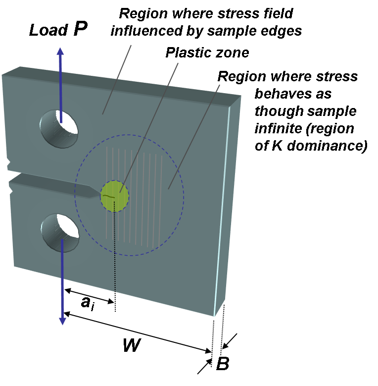
Figure 3. Finite cracked sample subjected to point load
Fracture and fracture toughness
Suppose the load on the specimen is increased until it breaks, i.e. fracture. The resistance to this fracture
may be characterized by the stress intensity at fracture, KIC, called the fracture toughness.
A KIC value represents a lower limiting value of the material's fracture toughness.
This value is used to estimate the relation between failure stress and defect size for a material in service where conditions of high tensile loading would be expected.
2. Objective and Approach
This experiment focuses on the mechanical characterization of epoxy-based energetic composite analogues incorporating ammonium perchlorate (AP) particulates and, in selected formulations, carbon nanotube (CNT) reinforcement. These materials serve as inert analogues for polymer-bonded energetic systems such as XTX 8003 and XTX 8004, which typically consist of 80 wt% PETN or RDX crystals coated with a silicone rubber binder (e.g., Sylgard 182 or 184) [7]. For safety and practicality, AP is employed as a non-energetic oxidizer analogue and embedded within a thermoset epoxy binder. The epoxy binder was chosen for its ease of processing, low cost, and ability to produce rigid, dimensionally stable specimens suitable for standardized mechanical testing. To investigate the effects of particulate concentration and nanoscale reinforcement on mechanical performance, epoxy–AP composites were fabricated with AP loadings ranging from 40 to 80 wt%, while epoxy–AP–CNT composites contained equivalent AP concentrations with a fixed 1 wt% CNT addition.
Each lab team is assigned specific formulations to evaluate under quasi-static and low-velocity impact loading conditions. For each composition, one specimen is prepared for tensile, compression, and Charpy impact testing, and four specimens are allocated for compact-tension testing to ensure adequate statistical representation. To enhance reproducibility, all teams conduct tests at the same particulate concentrations, resulting in a large dataset comprising hundreds of specimens across the four testing modes. All experiments are performed in accordance with ASTM D638 (tensile), ASTM D695 (compression), ASTM D5045 (fracture toughness via compact tension), and ASTM D6110 (low-velocity impact) standards.
3. Apparatus
Tensile, compression, and compact-tension tests are performed using an Instron 5900 Series Universal Testing Machine. The system is connected to a dedicated computer running Bluehill Universal software, which controls crosshead movement, executes pre-defined test protocols, and records force–displacement data in real time. The machine features a precision screw-driven crosshead that can be traversed vertically with high positional accuracy, allowing for both load-controlled and displacement-controlled testing.
Specimens are mounted between the crosshead and the stationary base using appropriate fixtures—clevis grips and dowel pins for compact-tension samples, and compression platens or tensile grips for other test modes. The applied load is measured by a 50 kN load cell mounted on the crosshead, offering a calibrated full-scale capacity of 50 kN with a rated accuracy of down to 1/1000 of capacity. The displacement is recorded through the crosshead extensometer system, ensuring accurate strain and crack-opening displacement measurements during testing.
The Instron 5900 is a high-precision testing system and must be operated with strict adherence to safety procedures. Testing is conducted under the supervision of a trained operator—either a teaching assistant or faculty member—who oversees specimen setup, calibration, and execution of each test. The machine is equipped with an easily accessible emergency stop button; operators should be familiar with its location prior to beginning any test. No other controls should be adjusted without explicit instruction from the supervising operator.
Before testing, both load and displacement channels are zeroed after specimen mounting to eliminate any preload or positional bias. This ensures that all load–displacement data originate from true zero conditions, providing consistent and reliable measurements for subsequent analysis.
Energetics Specimen
Fabricating the specimens for this experiment requires precise control over the mixing, casting, and curing processes to ensure consistency across all formulations. Each team is responsible for preparing its own set of specimens following the detailed procedure provided in the laboratory manual. In this study, the specimens consist of epoxy-based composites containing ammonium perchlorate (AP) particulates, with select formulations incorporating 1 wt % multi-walled carbon nanotubes (CNTs) as nanoscale reinforcement.
During fabrication, the thermoset epoxy resin (EPON 862) and W-curing agent are first combined in the manufacturer-recommended stoichiometric ratio. The AP particulates are then gradually incorporated to achieve a uniform dispersion within the matrix. For CNT-reinforced systems, multi-walled carbon nanotubes (MWCNTs) are first dispersed in acetone using ultrasonication and mechanical stirring to promote deagglomeration and uniform distribution. The epoxy resin is subsequently added to the CNT–solvent mixture, followed by a second ultrasonication cycle to enhance dispersion. The resulting mixture is passed through a rotary evaporator to remove residual solvent, after which the W-curing agent is added and mixed thoroughly by hand. The AP particulates are then introduced incrementally and manually blended to ensure uniform particle distribution throughout the resin.
The prepared composite is degassed under vacuum to eliminate entrapped air and then transferred into silicone molds for casting. Because transferring can reintroduce air bubbles, a secondary degassing step is performed immediately after casting. The samples are then cured under controlled temperature and time conditions to ensure complete crosslinking of the epoxy network. While great care is taken to minimize particle settling, partial sedimentation of AP crystals may occur at higher filler loadings due to density mismatch between the particles and the resin. Any visible non-uniformity or filler segregation should be documented, as these variations can influence local stiffness, crack initiation, and fracture behavior in the cured specimens.
Each batch is fabricated using AP particles with a controlled size range of approximately 90–200 µm to maintain consistency across formulations. The resulting epoxy–AP and epoxy–AP–CNT composites exhibit rigid, dimensionally stable geometries suitable for tensile, compression, and fracture testing in accordance with ASTM standards. The following specimen geometries and dimensions are used for mechanical testing:
- Tensile specimens conform to ASTM D638 Type IV, with a total length of 155 mm, a gauge length of 33 mm, and a width of 6 mm.
- Compact-tension specimens follow ASTM D5045, with a nominal width (W) of 25.4 mm and a thickness (B) of 6.35 mm.
- Charpy impact specimens conform to ASTM D6110, with dimensions of 125 mm × 12.5 mm × 4 mm (L × W × t) and a 45° V-notch having a radius of 2.54 mm.
- Compression specimens conform to ASTM D695. Cylindrical samples are fabricated with a diameter of: 0.5 inch = 12.7 mm, and a length of 1 inch = 25.4 mm.
All fabricated samples must be inspected for surface quality, dimensional accuracy, and absence of voids or cracks prior to testing. Any observed defects, air entrapment, or resin-rich or particle-rich regions should be recorded, as these factors may contribute to mechanical property variability among specimens.
Mechanical Characterization
Unlike the other experiments in AOE 3054 this experiment has a very specific procedure to ensure safety and agreement with the requirements of the ASTM standards. To meet these standards, the parameters for the 4 types of testing have been set as follows:
Tensile Testing
Tensile testing will be conducted in accordance with ASTM D638 at constant crosshead displacement rate of:
- 2 mm/min (strain rate of 0.12/min) for all compositions
Compression Testing
Compression testing will be conducted in accordance with ASTM D695 at constant crosshead displacement rate of:
- 2 mm/min (strain rate of 0.12/min) for all compositions
You will notice that same strain rate is used for both tension and compression experiments so that the modulus of elasticity under tensile vs compressive at quasi-static loading can be directly compared.
Compact Tension Testing
Compact Tension testing will be conducted in accordance with ASTM D5045 at constant crosshead displacement rate of 2 mm/min for all samples.
Impact Resistance Testing
Low velocity Charpy impact testing will be conducted in accordance with ASTM D6110 with non-instrumented pendulum hammer 5.4 J potential energy and 3.46 m/s impact velocity.
Tensile, Compression, and Compact Tension Testing Procedures
You should also refer to the Instron 5900 Series Testing Procedures document, which details the proper steps for safely operating the Instron Universal Testing Machine (UTM) using Bluehill Universal for tensile, compression, and compact-tension tests. This resource will help you identify where test information is recorded and how to properly export the raw data after completing each experiment.
Impact Resistance Testing Procedures
Details for the impact resistance testing are provided in Appendix 4.
4. Data Acquisition and Analysis
- Keep in mind that specimens are fragile !!!
-
Determine tensile properties including tensile modulus, tensile strength and fracture strain in accordance with ASTM D638 Section 11
- Measure specimen thickness (Keep in mind that specimens are fragile!) before each test.
- Provide stress-strain diagram. The stress is the ratio of the applied load over the original cross-sectional area, while the strain is the ratio of cross-head displacement over original distance between grips.
- Calculate tensile modulus of elasticity, tensile strength and nominal strain at fracture after testing your specimen (see Section 11 of ASTM D638).
-
Determine compressive properties including compressive modulus, compressive strength and failure strain in accordance with ASTM D695 Section 11
- Provide stress-strain diagram. The stress is the ratio of the applied load over the original cross-sectional area, while the strain is the ratio of cross-head displacement over original sample length.
- Calculate compressive modulus of elasticity, compressive strength
-
Determine the maximum load that the specimen can sustain and its fracture toughness in accordance with ASTM D5045
- Measure specimen thickness (specimens are fragile!) before each test.
- Provide load vs displacement plot for compact tension test.
- Determine the maximum load Pmax that the specimen sustained
- Determine PQ as per Fig.5 of ASTM D5045
- Calculate the conditional fracture toughness KQ as per sections 9.1.1 and A2.5
- Determine if KQ is a valid KQ fracture toughness value by following section 9.1.3.
-
Absorbed impact energy in accordance with ASTM D6110 or Appendix 4 - Impact Strength Testing.
- Measure specimen thickness (specimens are fragile!!) before each test.
- Calculate absorbed impact energy of your specimen.
-
Comparison of tensile and compressive test results
- Plot the stress vs strain diagrams for your tensile and compressive tests on the same figure.
- Compare tensile and compressive strength.
- Compare tensile and compressive modulus of elasticity.
- For all 3 items above, are the tensile and compressive quantities identical? Did you expect them to be?
-
Summary of your results
- Your results are part of a study to determine the variation of mechanical properties of mock PBX material as a function of sugar crystal concentration. Your results will be combined with those from the rest of the class to provide a large statistical data set. You will be given a datasheet template during the lab and a link to the shared Google form in the associated homework assignment.
5. References
- D. R. Drodge, D. M. Williamson, S. J. P. Palmer, W. G. Proud, R. K. Govier, The mechanical response of a PBX and binder: combining results across the strain-rate and frequency domains, Journal of Physics D: Applied Physics 43 (33) (2010).
- C. Siviour, P. Laity, W. Proud, J. Field, D. Porter, P. Church, P. Gould, W. Huntingdon-Thresher, High strain rate properties of a polymer-bonded sugar: their dependence on applied and internal constraints, Proceedings of the Royal Society of London A: Mathematical, Physical and Engineering Sciences 464 (2008) 1229-1255.
- F. P. Bowden, A. D. Yo_e, Initiation and growth of explosion in liquids and solids (republ.1985). Cambridge, UK: Cambridge University Press (1952).
- Hu, Z., Luo, H., Bardenhagen, S.G., Siviour, C. R., Armstrong, R. W. and Lu, H., Exp Mech (2015) 55: 289.
- Sengezer, E. C and Seidel, G. D, Application of Piezoresistive Nanocomposite Binders for Real Time Embedded Sensing of Strain and Damage in Energetic Materials, 58th AIAA/ASCE/AHS/ASC Structures, Structural Dynamics, and Materials Conference, AIAA SciTech, (AIAA 2017-0122).
- Sengezer, E. C and Seidel, G. D., Structural Health Monitoring of Nanocomposite Bonded Energetic Materials through Piezoresistive Response, AIAA Journal-2017-02J056104, manuscript submitted.
- Gibbs, T. R., Popolato A., LASL Explosive Property Data, University of California Press, 1980.
- P. J. Rae, S. J. P. Palmer, H. T. Goldrein, J. E. Field, A. L. Lewis, Quasi-static studies of the deformation and failure of PBX 9501, Published 8 September 2002
- Field J, Hot spot ignition mechanisms for explosives, Acc. Chem. Res., 1992, 25 (11), pp 489-496