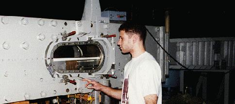
Supersonic wind tunnel
The Virginia Tech 23 x 23 cm supersonic/transonic wind tunnel was designed and originally constructed at the NASA Langley Research Center. In 1958, the tunnel was purchased by Virginia Tech and put into operation in 1963. During recent years, several modifications were introduced into the air pumping, tunnel control, and instrumentation equipment which increased the capabilities of the facility.
The air pumping system consists of an Ingersoll-Rand Type 4-HHE-4 4-stage reciprocating air compressor driven by a 500 hp, 480V Marathon Electric Co. motor. The compressor can pump the storage system up to 51 atm. A drying and filtering system is provided which includes both drying by cooling and drying by absorption. Air storage system consists of two tanks with a total volume of 23 m. Tunnel control system includes quick opening butterfly valve and a hydraulically actuated pressure regulating 30.5 cm diameter valve.

The settling chamber contains a perforated transition cone, several damping screens, and probes measuring stagnation pressure and temperature. The nozzle chamber is interchangeable with two-dimensional contoured nozzle blocks made of steel. The tunnel is equipped with three complete nozzle chambers which presently are fitted with the nozzles for the Mach numbers 2.4, 3.0, and 4.0.

The working section of the tunnel is equipped with a remotely controlled model support which allows one to vary the position of a model in the vertical plane. An arrangement for side wall model mounting is also available. An extractable mechanism can be provided for supporting the model during the starting and stopping of the flow. Due to large doors containing the windows in the nozzle and working sections a very good access to the model is ensured.

Instrumentation
A 30 cm Schlieren apparatus uses two parabolic mirrors and air cooled high pressure mercury lamp. Shadowgraph pictures can be taken either with a direct-shadowgraph system or with a focused shadowgraph arrangement. A 1 microsecond spark source is used for this purpose. Interferograms may be taken with a laser-based single plate interferometer system and a CCD camera.
To record flow phenomena of very rapid action and short time duration, the Hycam high speed motion picture camera can be used. The camera can be optically coupled with either Schlieren or shadowgraph apparatus. Operating speed limits are from 1,000 to 45,000 pictures per second. A six-component force and moment balance is also available.
The main pressure measuring system includes a PSI Model 780B electronically scanned pressure system. The system is IBM PC computer controlled and presently can handle 32 pressure inputs (0 to 1 atm) simultaneously but, if a need arises, it can be expanded up to 512 pressure inputs. Pressure data rate is up to 20,000 measurements per second and the accuracy is 0.1% of span. In addition to the electronically scanned pressure system, there are two Scanivalve systems available, each allowing to record up to 48 pressures (0-3 atm) during a run of a few seconds duration.
Temperature and heat transfer measurements can be made using an automatic multipoint thermocouple reference system and high-speed potentiometric recorders.
Data acquisition is all IBM PC based using modern software such as LabView.
Technical specification of the tunnel:
| Test section size | 23 x 23 cm |
| Stagnation pressure | 3 - 20.5 atm |
| Mach number | 2.4 - 4 and 0.2 - 0.8 |
| Reynolds number per meter | 2 x 10⁶ to 5 x 10⁶ |
| Run duration, depending on Mach number and stagnation pressure | 8 - 60 sec |
| Dewpoint | below -40C |
| Maximum model diameter at M=3 | 9 cm |
| Storage tank volume | 23 m3 |
| Maximum air pressure in the storage tanks | 51 atm |
| Total power rate of the compressor plant | 500 hp |


